![]()
Site Search
Please enter a keyword
- Crystal Unit
- Crystal Oscillator
- Frequency Synthesizer
- Signal Generator
- Millimeter-Wave Converter
- Synthetic Quartz Crystal
- Optical Component
- QCM Sensor
- Outgas Analysis System
- Ultrasound Probe (Transducer)
- SAW Devices (Manufactured by NDK SAW devices Co., Ltd.)
-
Space
-
Infrastructure / Industrial Equipment
-
Automotive
-
Mobile
-
AV / OA, Medical, Healthcare, Household Appliance
-
Search from Connectivity Standards
Product Search
Technology
What is Crystal Oscillator for Space Development?
1. Impacts of Electronic Equipment on Outer Space
When electronic equipment is used in space, such as satellites, it must withstand extremely severe operating environments, such as the effects of radiation and severe temperature changes.
If a satellite fails, it cannot be repaired, and there are significant impacts such as cost losses (launch costs for HII-A rockets: approximately 10 billion yen, satellite manufacturing costs: several tens of billions of yen) and satellite becomes to space debris ( Fig. 1). Therefore, high reliability is required for components of space applications.
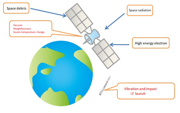
Fig.1 Image of impact on spacecraft in space environment
(The red letters in the frame are considered items in the design.)
2. Requirements for space-use components
General requirements for components for space applications are listed below.
・ Operating temperature range :-55 ℃ ~ +125 ℃
・ Hermetic package
・ High vibration resistance
・ Control of outgas and flammability
・ Long-term reliability
・ Radiation tolerance
・ Lot assurance test
・ Traceability at lot level
3. Policy for reliability assurance of oscillators for space use
High reliability is guaranteed by incorporating the following four points into the design and quality control, including the requirements for components for space applications, as oscillators for onboard satellites.
(1) Reliability assured at the mounted onboard component level
(2) Oscillator Structure Considering Environmental Resistance Performance
(3) Implement thorough process control (check and inspect each process)
(4) Conducted quality verification tests for screening and Lot assurance
Common Specification for Reliability Assurance Mixed Integrated Circuits for Space Development: Applied to JAXA-QTS-2020
Each item is described in detail below.
(1) Reliability assured at the onboard component level
We guarantee the reliability of oscillators by adopting JAXA certified parts and MIL certified parts (Space grade) whose reliability is guaranteed at the part level, or parts whose quality verification test is equivalent to MIL certified parts.
In particular, for radiation-resistant (SEE and TID) (*1), we use semiconductors with guaranteed radiation-resistance of a certain level or higher as semiconductor components, and for crystal unit, we use crystal blank cut from high-quality quartz raw stone, which is the same as JAXA certified crystal unit, which has a proven track record for space use.
As an oscillator, a radiation resistance test (TID) is conducted during the quality confirmation test to ensure quality.
| (*1)Radiation Tolerance | |
| a) SEE: Single Event Effect | |
| Single-shot high-energy particles are injected into semiconductor devices and are affected by their ionization action. Semiconductor failure modes include SEL (single event latch-up: transient failure, bit inversion, etc.) and SEU (single event setup, permanent failure, etc.). | |
| b) TID: Total Dose | |
| A large amount of low energy particles enter the semiconductor device and are affected by their ionization action. The device gradually degrades such as leakage current and threshold changes | |
(2) Oscillator Structure Considering Environmental Resistance Performances
A characteristic feature of required specifications for this oscillator is its wide range of operating temperatures. If the oscillator is repeatedly subjected to low and high temperatures, the solder may deteriorate due to heat stress on the part mount (soldering part). Some active parts are large in size and affected by heat stress. Electrical connections are made not by soldering, but by adhesive fixation and wire bonding.
Because of its small size, passive components are mounted with proven soldering for space use.
Crystal unit has a double-sealed structure that uses a packaged crystal unit to ensure the environmental resistance performance of crystal unit itself and improve performance of the oscillator. In addition, we have adopted a structure with a large number of terminals for the purpose of dispersing vibrations and shocks during launch.
The structure described above has proven to be a component for space use, and by adopting these components, quality in terms of structure has been secured. (Fig. 2)

Fig.2 Oscillator Structure Diagram
(3) Implement thorough process control (check and inspect each process)
As well as ISO9001 (Quality Management System), we have established a quality assurance program plan that conforms to the General Common Specifications (JAXA-QTS-2000) for common components for space development, and we control the quality of processes through reliable operation.
(4) Conducted quality verification tests for screening and Lot assurance
JAXA standard (JAXA-QTS-2020) conforming to MIL-STD-883 is applied.
a) Screening
In order to reject the initial defects, we conduct a full number of inspections for the items shown in Table 1.
Table 1 Screening
| Order | Test item | Test Method/Condition (*2) |
| 1 | Stabilized bake | 1008 Condition C (150°C, 24 hours) (*3) |
| 2 | Heat cycle test | 1010 Conditions C |
| 3 | Mechanical impact test | 2002 Conditional B Y1 directions only |
| 4 | Visual inspection | |
| 5 | Particle collision noise detection test | 2020 Conditions A |
| 6 | Series numbering | |
| 7 | Radiographic examination | 2012 Y1 and X2 directions |
| 8 | Midpoint electrical parameter test (Before burn-in, Group A, Subgroup 1) |
Frequencies, current consumption, Outputs waveform, etc. |
| 9 | Burn-in test | 1015 (240 hours, +125 °C) |
| 10 | Midpoint electrical parameter test (After burn-in, group A, Subgroup 1) |
Frequencies, current consumption, Outputs waveform, etc. |
| 11 | Frequency aging | Apply MIL-PRF-55310 4. 8.35.1 +70 °C, 32 days |
| 12 | Airtightness test | 1014 |
| 13 | Final electrical parameter test 1) 25°C (Group A, Subgroup 1) 2) Maximum and minimum operating temperatures (Group A, Subgroup 2, 3) |
Frequencies, current consumption, Outputs waveform, etc. |
| 14 | External visual inspection | 2009 |
(*2) 4 -digit number indicates MIL-STD-883 test procedure number.
(*3) Stabilized bakes shall be conducted in-process inspections and omitted in screening.
b) Quality verification test for Lot assurance
To the sampling test for the items shown in Table 2 as a quality confirmation test to assure the quality at the lot level
We are doing this.
Table 2 Quality verification tests
| Group | Sub Group |
Test item | Test method(*4) | Test conditions |
| A | 1 | Electrical Characteristics Inspection (Normal Temperature) | - | Frequencies, current consumption, Outputs waveform, etc. |
| 2 | Electrical Characteristics Inspection (Low temperature) | |||
| 3 | Electrical Characteristics Inspection (High temperature) | |||
| B | 1 | Dimensional inspection | 2016 | |
| Lead strength test | 2004 | Conditions B | ||
| Confidentiality test | 1014 | Conditions A2 and C1 | ||
| Examination of internal water vapor level | 1018 | |||
| 2 | Solvent resistance test | 2015 | Solvent a | |
| Internal Visual and Mechanical Inspection | 2013, 2014 | |||
| Bond strength test | 2011 | Condition C or Condition D | ||
| Die peel strength test | 2019 | |||
| 3 | Solderability test | 2003 | +245℃±5℃ | |
| C | 1 | Steady state operation life test | 1005 | +125℃ 1,000h |
| End-point electrical parameter test | - | Group A Testing Subgroup 1, 2, 3 | ||
| 2 | Visual inspection | - | According to the inspection standards of Test Method 2009 | |
| Heat cycle test | 1010 | Conditional C 100 cycles | ||
| Impact test | 2002 | Conditions B | ||
| Vibration test | 2007 | Conditions A | ||
| Airtightness test | 1014 | Conditions A2 and C1 | ||
| Particle collision noise test | 2020 | |||
| External visual inspection | - | According to the inspection standards of Test Method 2009 | ||
| End-point electrical parameter test | - | Group A Testing Subgroup 1, 2, 3 | ||
| 3 | Electrostatic fracture test | 3015 | ||
| End-point electrical parameter test | - | Group A Test Subgroup 1 | ||
| D | 1 | Thermal shock test | 1011 | Conditional B 15 cycles |
| Moisture resistance test | 1004 | |||
| Airtightness test | 1014 | Conditions A2 and C1 | ||
| Visual inspection | - | Test method 1010 According to the test standards of or1011 | ||
| E | 1 | Radiation resistance test n | 1019 | |
| End-point electrical parameter test | - | Group A Test Subgroup 1 |
(*4)4 -digit number indicates MIL-STD-883 test method number.
As described above, we guarantee high reliability as oscillators for onborad satellites through quality control in parts, structure, process control, and assurance tests. As a result, we have been certified by the Japan Aerospace Exploration Agency (JAXA) as conforming to JAXA-QTS-2020 of common specifications for reliability assurance mixed integrated circuits for space development.
The external appearance of the oscillator for space is shown in Fig. 3, and the electrical characteristics are shown in Table 3.
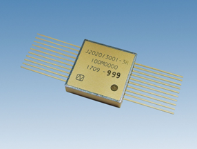
Fig. 3 Space Oscillator Appearance (15.8 x 15. x 3.5 mm)
Table 3 Electrical performance
| Frequency range | 41 ~ 100 MHz |
| Supply voltage | DC +3.3 V ± 5 % |
| Frequency tolerance | ± 15 ppm |
| Frequency/temperature characteristics | ± 50 ppm |
| Power consumption | 40 mA max. |
| Output level | ACMOS |
| Long-term frequency stability | ±3 ppm/year (year 1) and ±1. 5 ppm/year (year 2 or later) |
| Operating temperature range | -45 ~ +125 ℃ |
4. Summary
In the future, we will consider expanding the frequency and adding packages as required.
We will also apply the structure and quality control methods established in this design to highly reliable products in other markets.