![]()
Site Search
Please enter a keyword
- Crystal Unit
- Crystal Oscillator
- Frequency Synthesizer
- Signal Generator
- Millimeter-Wave Converter
- Synthetic Quartz Crystal
- Optical Component
- QCM Sensor
- Outgas Analysis System
- Ultrasound Probe (Transducer)
- SAW Devices (Manufactured by NDK SAW devices Co., Ltd.)
-
Space
-
Infrastructure / Industrial Equipment
-
Automotive
-
Mobile
-
AV / OA, Medical, Healthcare, Household Appliance
-
Search from Connectivity Standards
Product Search
Summary
Equivalent Circuit and Electrical Characteristics
| The electric equivalent circuits of a crystal unit is generally represented as shown in Fig.7, and the four equivalent constants are labeled as follows: L1: Equivalent series inductance C1 : Equivalent series capacitance R1: Equivalent series resistance C0: Shunt capacitance |
 Fig. 7 Electric Equivalent Circuit of a Crystal Unit |
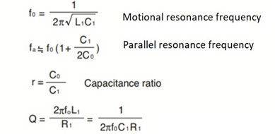
| The main characteristics of a crystal unit is derived by using these equivalent constants. As an example, Fig. 8 shows the frequency characteristic of impedance. Typical frequencies and performances of crystal units are shown below.
|
|
| The general crystal oscillation circuit is capacitive, and can be treated as series circuits with a negative resistance (-R) and load capacitance (CL) as shown in Fig. 9 |  Fig. 9 Relationship between a Crystal Unit and the Oscillation Circuit |
| When the load capacitance values are CL and series , fL and fS, respectively, the following relationship is established.
Fig. 10 shows an example. An overtone crystal with a smaller C1 value than a fundamental wave has a smaller frequency change rate with respect to CL than a fundamental wave. The C1 value of small-size crystal units is smaller than that of large-size crystal units with the same frequency. For this reason, frequency change rate to the load capacitance is smaller for a small-sized crystal units. When the load capacitance (CL) is connected to the crystal unit in series as shown in Fig. 9, the equivalent resistance increases according to the following formula.
|
|