![]()
Site Search
Please enter a keyword
- Crystal Unit
- Crystal Oscillator
- Frequency Synthesizer
- Signal Generator
- Millimeter-Wave Converter
- Synthetic Quartz Crystal
- Optical Component
- QCM Sensor
- Outgas Analysis System
- Ultrasound Probe (Transducer)
- SAW Devices (Manufactured by NDK SAW devices Co., Ltd.)
-
Space
-
Infrastructure / Industrial Equipment
-
Automotive
-
Mobile
-
AV / OA, Medical, Healthcare, Household Appliance
-
Search from Connectivity Standards
Product Search
Oscillation Circuit Evaluation Methods
What is "Drive Level" (1) <Overview>
The drive level is the power supplied to the crystal unit for oscillation. The drive level is calculated by the following equation.
DL (μW) = RL (Ω)×i2 (mA)
DL: Drive Level
RL: Load resonance resistance of crystal unit
i: Current value flowing through crystal unit (effective value)
The specifications of each crystal unit have a drive level standard, and the upper limit of the drive level for which operation is guaranteed is defined.
The problem of concern when the upper limit is exceeded is abnormal oscillation effect on oscillation frequency) due to coupling with unwanted response (spurious mode). This problem is explained below.
The AT-cut crystal unit uses the thickness-shear mode as the oscillation mode of the main vibration, but there are many other unwanted response (spurious) modes such as Flexure, Face-shear and so on. Fig. 1 shows the oscillation modes of the AT-cut crystal unit.
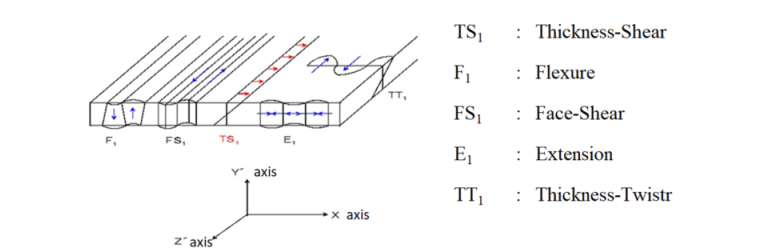
Fig. 1. Vibration modes of AT-cut crystal unit
The frequency of these unwanted response (spurious modes) may be combined with the frequency of the oscillation mode of the main oscillation at a specific temperature, which affects the oscillation frequency.
Coupling of unwanted response and main vibrations is likely to occur when the drive level is excessively high for the specifications.
Fig. 2 shows how the oscillation frequency temperature characteristics differ between the normal drive level (drive level within the standard range) and the excessive drive level (drive level outside the standard range).
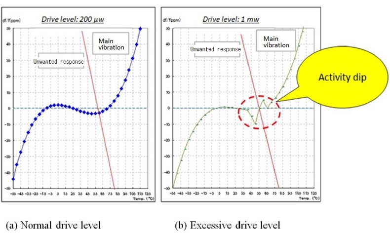
Fig. 2. Oscillation Frequency Temperature Characteristics
When the drive level is normal, a smooth cubic curve is drawn as shown in Fig. 2(a).
However, when the drive level is excessively high, a phenomenon (called Activity dip) in which the oscillation frequency changes rapidly over a specified temperature range is likely to occur as shown in Fig. 2(b).
In order to prevent Activity dip, we propose circuit constants that fall within the drive-level specification in circuit analysis.