![]()
Site Search
Please enter a keyword
- Crystal Unit
- Crystal Oscillator
- Frequency Synthesizer
- Signal Generator
- Millimeter-Wave Converter
- Synthetic Quartz Crystal
- Optical Component
- QCM Sensor
- Outgas Analysis System
- Ultrasound Probe (Transducer)
- SAW Devices (Manufactured by NDK SAW devices Co., Ltd.)
-
Space
-
Infrastructure / Industrial Equipment
-
Automotive
-
Mobile
-
AV / OA, Medical, Healthcare, Household Appliance
-
Search from Connectivity Standards
Product Search
Oscillation Circuit Evaluation Methods
What is "Startup Time" (1) <Overview>
Although the definition of the startup time varies depending on the case, the standard definition of the startup time in NDK is "the time from the application of the oscillation bias voltage to the oscillation stage until the voltage amplitude of the oscillation saturates".
The standard is to measure in units of 1 ms for circuits in the MHz band and 0.1 s for circuits in the kHz band.
The theoretical formula is as follows:
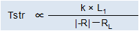
Tstr: Startup time
k: Proportionality constant
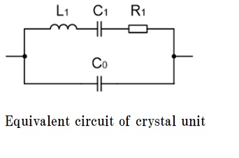
L1: Equivalent motional inductance of crystal unit (See crystal unit equivalent circuit)
|-R|: Negative resistance of circuit (absolute value)
RL : Load resonance resistance of crystal unit
Examples of standard startup time measurements(oscilloscope images) are shown in Fig.1 and 2.
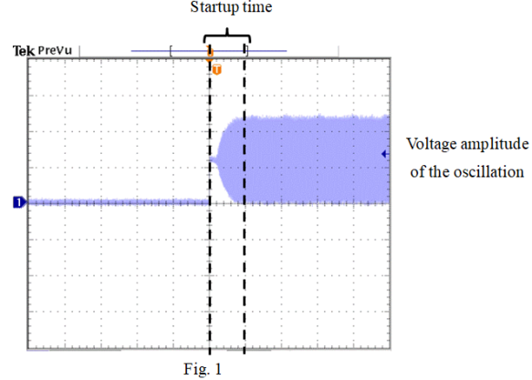
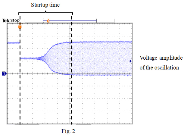
Fig. 1: When the voltage of the oscillation stage rises from 0V to the oscillation biasing voltage.
Fig. 2: When the voltage of the oscillation stage drops from the VDD voltage of the IC to the oscillation bias voltage.
In some cases, the start point of the measurement of the start time is set to "the time when the voltage is applied to the power supply terminal (VDD terminal) of the IC" at the request of the customer.
An example of the startup time measurement (an oscilloscope image) is shown in Fig. 3.
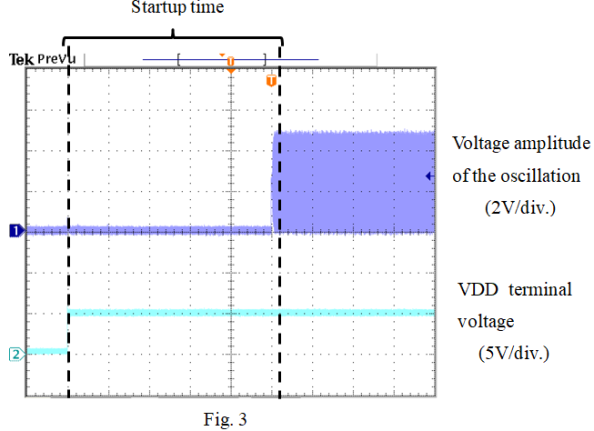
Unless otherwise requested, NDK measures the startup time using the method shown in Figs. 1 and 2.