![]()
Site Search
Please enter a keyword
- Crystal Unit
- Crystal Oscillator
- Frequency Synthesizer
- Signal Generator
- Millimeter-Wave Converter
- Synthetic Quartz Crystal
- Optical Component
- QCM Sensor
- Outgas Analysis System
- Ultrasound Probe (Transducer)
- SAW Devices (Manufactured by NDK SAW devices Co., Ltd.)
-
Space
-
Infrastructure / Industrial Equipment
-
Automotive
-
Mobile
-
AV / OA, Medical, Healthcare, Household Appliance
-
Search from Connectivity Standards
Product Search
Oscillation Circuit Evaluation Methods
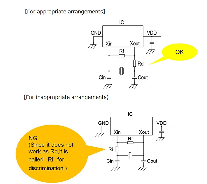
Appropriate arrangement of damping resistor (Rd)
Make sure to place the damping resistor (Rd) on the output terminal side of the IC.
If there is a resistor on the input terminal side of the IC, that resistor does not act as an attenuator very much because of the impedance height of the input terminal.
The notation in the IC data sheet regarding "which terminal is an input terminal or an output terminal" varies depending on each IC manufacturer, and is not uniform.
When it is difficult to determine which damping resistor (Rd) should be placed in the oscillator circuit design, please contact the IC manufacturer.
In our circuit analysis report, the input terminal of the IC is called "Xin," and the output terminal is called "Xout."
Where to place the damping resistor (Rd) is shown below.