![]()
Site Search
Please enter a keyword
- Crystal Unit
- Crystal Oscillator
- Frequency Synthesizer
- Signal Generator
- Millimeter-Wave Converter
- Synthetic Quartz Crystal
- Optical Component
- QCM Sensor
- Outgas Analysis System
- Ultrasound Probe (Transducer)
- SAW Devices (Manufactured by NDK SAW devices Co., Ltd.)
-
Space
-
Infrastructure / Industrial Equipment
-
Automotive
-
Mobile
-
AV / OA, Medical, Healthcare, Household Appliance
-
Search from Connectivity Standards
Product Search
Oscillation Circuit Evaluation Methods
What is "Drive Level" (3) <Improvement Methods>
If the drive level of the circuits exceeds the upper limit of the guaranteed drive level (as defined in the specifications of each crystal unit), problems such as those described in drive level (1) may occur, and the drive level must be lowered. The following options are available for improvement.
(1) Reduce the capacitance of the external capacitor (Cin, Cout)
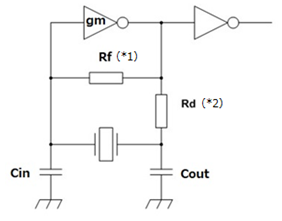
(*1) Feedback Resistance: properly feeds back current and signal from the output terminal to the input terminal of the IC
(*2) Damping Resistance: suppresses oscillation amplitudes
The relation between the drive level when Cin and Cout are changed and external capacitor is shown below.
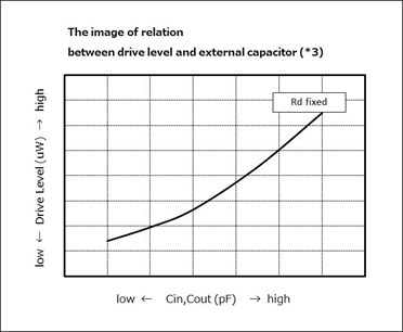
(*1) Graph measured under the condition: Cin = Cout.
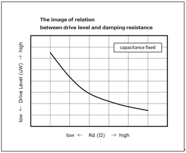
(2) Increase the value of damping resistance(Rd)
The relation between the drive level when the damping resistance is changed and the damping resistance is shown below.
If the above methods cannot be improved sufficiently, we will consider whether the crystal unit specifications of the drive level can be changed.